-40%
Oscilloscope Clock 3ACP7A CRT Cathode ray tube scope clock OSC7.1 auto time dat
$ 184.8
- Description
- Size Guide
Description
MADE IN THE USAA youtube video is interesting but it does not actually show the color shading in reality, it is only captured on camera.
A 3ACP7A CRT with blue/yellow phosphor. - YouTube
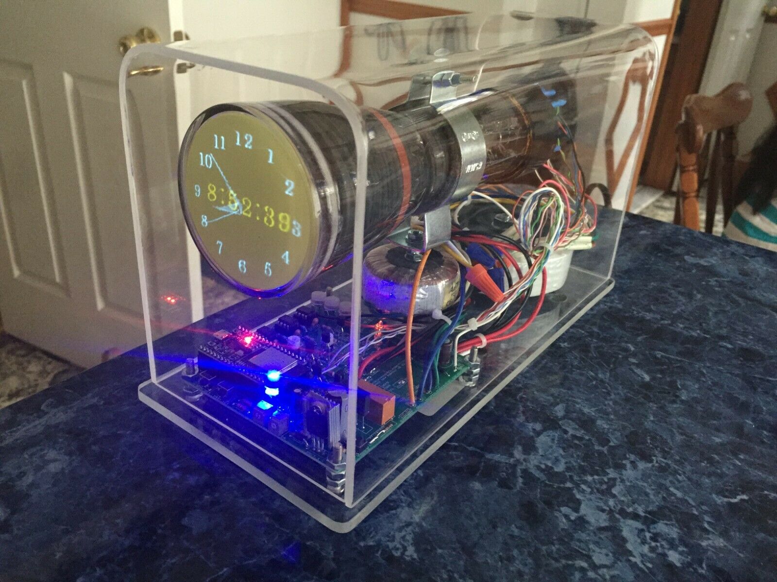
This is a 3ACP7A CRT which has an afterimage due to the two layered phosphor (blue/yellow)
This is my newest version, OSC7.1, with a built in Wifi connection for automatically extracting the time,
day & date from network time servers.
This is designed to drive 5" or even larger CRTs and many types can replace this one, such as 3ACP1
3BP1, 3FP7, 3JP7 and other similar types.
Homemade, not a commercial product.
This measures about 7.5" W x 8" H x 12” D.
The clear acrylic shroud is
not attached, but sits loose on top of the plexiglass base.
The board has pots to adjust vertical & horizontal height / width, focus, astigmatism, brightness, and
vertical and horizontal centering.
Automatically sets for 50/60HZ. The display alternates every ten seconds between digital and analog
style.
Display also moves
slightly every six seconds to help prevent "burn in" of the crt. The microcontroller
and all chips are in
sockets for easy replacement, and all
the components are
replaceable/repairable
with some soldering
skills and basic component identification
.
This "old school" tech has been salvaged from obsolescence
by marrying it to new digital tech.
It is an
entirely homemade/handmade product, including the base and shroud, which I thermoform
from plexiglass stock, and
the firmware the microcontroller is programmed with, which
is my own
original code.
Below are the operating
instructions. I will ship it anywhere in the world, but I
cannot be responsible
for problems and/or delays caused by
customs in your
country.
International buyers,
please send your address for a shipping quote. It can be set for operation on
120VAC (U.S. standard) or 240VAC (some
other countries)
It is an entirely
homemade novelty craft
project from my workbench.
Some points of interest:
All the components on my clocks / kits are replaceable/repairable because they are all standard
size, not surface mount.
The IC's or "chips" are socketed so they can also be replaced easily, by simply unplugging the chip and plugging in the replacement.
In many cases, I will repair the clock free for any reason if you ship it back to me - i.e., if a
component fails or is damaged (except the tube(s))
All of my clocks use standard electric service (do not need a separate power supply) and
can be set for 120VAC (U.S.) or 240VAC (others)
_________________________________________________________________________________________________________________________________
Instructions for OSC7.1:
For the quick start video please use the youtube link here:
https://www.youtube.com/watch?v=oXqGBzmSzus&t=16s
When the scope clock is plugged in, the blue led & the small led on the module should light immediately.
To start, press the "slow set" button (immediately after power on) and hold for up to three
seconds until the relay clicks and the neon bulb lights
The relay should click on, neon light should light, and in a few minutes the screen should display time.
The display will go to run mode (clock face) or "Oscilloscope clocks"
Press slow set button again to start, and use fast set & slow set to set the time.
Toggle button will toggle the display on & off, just press once.
From the clock face screen, press slow set & toggle simultaneously to display the day & date.
From the date screen, press fast set to return to the time screen.
From the date screen, press slow set & fast set simultaneously to enter the Menu screen.
In the Menu screen, use fast set to select the line indicated by the arrow, and use slow set to
change the selection.
When the Menu settings are correct, press toggle once to exit and return to the clock face screen.
To connect the clock to your network via wifi, start from power on, unplug and wait a few minutes if it's already powered on.
From power on (blue led & led on module lit), press & hold the "toggle" button for three seconds to enter AP mode.
Use your device to look for the AP "WifiModule" on your networks.
Connect to this AP, and when connected, open your browser and type "192.168.4.1" in the address bar.
Enter your network name or SSID and your network password.
Click "Submit" button and the confirmation page should appear.
Within a few minutes, the clock should connect to the network and the neon bulb (high voltage) should light.
If the clock doesn't connect after several minutes, try resetting the chip by pressing the miniature button on the ESP32 board
marked "EN" or alternatively, just unplug the clock and wait a few minutes, then plug it back in and it should connect.
The time should appear. If incorrect, press the "fast set" & "toggle" buttons simultaneously to refresh the time.
To erase the network name & password, press and hold toggle button while powering the clock on, and release after three seconds.
Wifi should go into AP mode, allowing connection to enter new credentials.
From the clock face, press fast set & toggle simultaneously to refresh the time.
To set the sleep/wake times, press fast set & slow set, and the screen will appear for setting the "on" time.
Use fast set to choose the display on (wake) time (hours only).
Press toggle once to enter the "off" time screen.
Fast set & slow set to select the off time, and toggle once to exit to clock face screen.
Please note that in order to program a PM "off" time, you will need to pass 12:00 to get into the PM hours.
Time Zones :
0=UTC
1 = EST
2 = CST
3 = MST
4 = PST
5 = AKST
6 = HAST
7 = BST
8 = CEST
9 = MSK
10 = PHT
11 = ACST
12 = GST
13 = AEST
